From pv magazine 04/2021
Procuring PV modules that are designed to resist microcrack formation and propagation can help solar asset owners and investors reduce the risk of their projects underperforming in the field. There are merits and drawbacks to different module designs and technologies in terms of microcrack resistance. As a part of its PV Module Product Qualification Program (PQP) PV Evolution Labs (PVEL) has illuminated which designs can close the quality gap when it comes to cell cracking.
Understanding microcracks
Crystalline silicon (c-Si) solar cells are essentially paper-thin pieces of glass. They will crack when subjected to thermal and/or mechanical stress that ruptures the silicon wafer. Often these microcracks occur as a result of the manufacturing process, particularly during the wafer cutting, cell cutting, cell soldering, and lamination steps. Additionally. improper PV module handling during transportation, installation, maintenance, and even cleaning can also subject PV modules to mechanical stresses that result in cell cracks.
Environmental conditions are a factor in microcrack creation – and, importantly, microcrack propagation. For example, high wind events, snow accumulation and hail can all subject PV modules to significant mechanical stress that causes acute damage. While less dramatic than extreme weather events, simple daily temperature fluctuations, and seasonal freeze-thaw cycles can also result in cracking. Over time, the thermal stresses that accompany normal variations in ambient temperature magnify cell-level damage by widening, expanding and articulating existing microcracks.
The long-term microcrack articulation process is critical to understanding PV module health. Microcracks typically are not problematic unless – and until – the damage restricts the flow of current through the cell and creates an inactive area. When the flow of current is restricted, the module will produce less energy. Eventually, a local hotspot may form in the damaged area of the cell. Hotspots can accelerate backsheet degradation and delamination, eventually increasing the risk that ground and arc faults will occur.
Crack detection
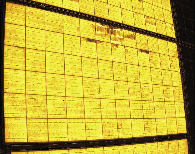
Solar cell cracks and damage are usually not visible to the naked eye on the surface of a PV module. Electroluminescence (EL) imaging or other advanced imaging techniques are almost always necessary to identify both cracks and microcracks. Because they are electrically inactive, cell cracks appear as dark, discoloured, broken lines or areas in EL images. Different shapes, sizes and types of cracks affect PV modules in different ways, although in PVEL’s lab and field-testing experience, branching cracks (also known as dendritic cracks) that spread through cells as modules age in the field are usually the most destructive.
PQP findings
The mechanical stress sequence (MSS) is one of the reliability tests in PVEL’s PV Module PQP. MSS simulates field conditions in a controlled laboratory environment through the combination of static and dynamic loading with thermal cycling and humidity freeze in environmental chambers. PVEL’s process is engineered to create, articulate and propagate field-representative cracks in susceptible modules. The test is aligned with the forthcoming IEC 63209 technical specification for the extended reliability testing of PV modules.
PVEL’s MSS findings demonstrate that crack susceptibility is nuanced. Several new technologies are inherently less susceptible to cracking, but some older technologies may perform better than their newer counterparts. Ultimately, crack susceptibility depends on the specific components and manufacturing techniques employed in PV module production. In other words, a PV module with an innovative and robust design could still be susceptible to cell cracks, especially if it is poorly constructed or uses low-quality material components.
Light-reflecting film
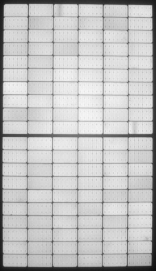
The use of light-reflecting film (LRF) in PV modules is a powerful example of the unintended consequences that can accompany technical advancements if other aspects of the module design, such as encapsulant thickness, are not modified in tandem.
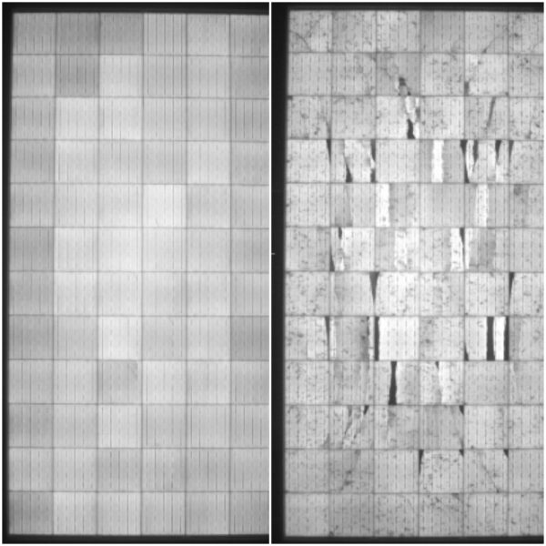
While the BOM without LRF (left) showed minimal damage following MSS, the BOM with LRF (right) had significant cell cracks and inactive areas.
PVEL’s findings as to the potential impacts of LRF in terms of cell cracking may surprise even industry veterans – and indeed are the most recent new insight garnered through testing. LRF increases the amount of light reflected into a PV module to improve power output. However, LRF can increase microcrack susceptibility due to thermal expansion as shown in the images (above). When LRF and glass components expand and contract at different rates as temperature fluctuates, cells may be subjected to crack-inducing stress.
Mono vs. multi
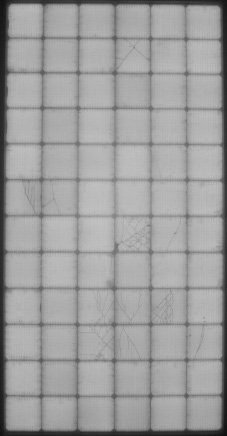
In recent years the solar industry has rapidly transitioned from multicrystalline silicon solar cells to monocrystalline silicon cells, in a shift that surprised many analysts who expected that multicrystalline would have a larger market share than its current (and dropping) share of about ten percent.
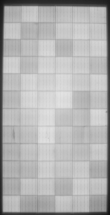
The most obvious benefit of this transition is, of course, higher efficiency modules. PVEL’s MSS test results point to another benefit: monocrystalline cells are inherently less susceptible to cracking than multicrystalline. However, if monocrystalline modules are produced using substandard components or a poor quality control process, they may be significantly more susceptible to cell cracking, as can be seen in the image (below).
Large vs. small
Manufacturing shifts to larger format and higher-powered PV modules are among the most hotly debated technology advancements in the solar industry today. While larger solar modules – and the larger wafers they necessarily contain – are driving exciting power class improvements, they could also increase cracking risks.
One key issue to keep in mind in terms of cracking in large-format modules is that the larger silicon wafers used in these modules will be subjected to pressures over a larger surface area. What is more, the modules may be subject to more deflection during high wind and heavy snow loads. Finally, in an effort to reduce the weight of these modules, some manufacturers use thinner glass and/or thinner frames, a practice that can reduce rigidity and durability. These three factors all pose demonstrable microcrack susceptibility risks.
The challenges posed by increased size can be observed by comparing MSS results from standard-size PV modules. The bill of materials of the PV modules in the images (below) are nearly identical – one is a 144-cell design and the other is the same manufacturer’s 120-cell design. While both performed relatively well in MSS, the 144-cell version experienced more cell cracks than the 120-cell version. A larger surface area can result in more deflection during mechanical loading, which may, in turn, generate cracks.
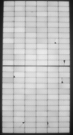
The PV modules pictured above have nearly identical BOMs. However, the 144-cell version of this BOM (right) proved more susceptible to microcracks than the 120-cell version (left).
Cell cutting
In some cases, full cell modules are more susceptible to cell cracking than modules made with half-cut cells. As is the case with larger modules, larger full cells have a larger surface area that needs to withstand mechanical pressure during static mechanical load. However, it must be stressed to manufacturers that improper cell cutting can create microcracks.
Cell interconnection
Microcracks become a safety and performance issue when they create inactive areas in cells. PVEL has observed a significant difference in inactive areas due to cell cracks for modules with five-busbar cells and 12-busbar cells.
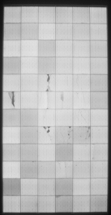
In the five-busbar example shown in the images (below), the cracks have clearly created inactive zones where they have actually separated portions of the cells from the busbars. For the 12-busbar example, similar cracks have occurred, but due to the higher number of busbars spanning the cells, few inactive areas can be seen.
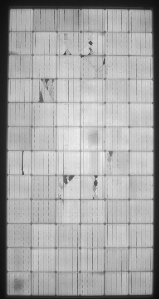
Both the 12-busbar (left) and five-busbar (right) PV modules suffered cracks during MSS testing, but the five-busbar PV module has significantly more inactive areas.
While resistance to power loss from cracking is one of the innate advantages of multi-busbar modules, it is important to note that some five- and six-busbar modules have also performed well in PVEL’s MSS testing.
The advancement of photovoltaic module technology comes with both opportunities and risks. While PVEL’s test results to date indicate that design and material innovations like half-cut cells and multi-busbars can increase microcrack resistance, other advancements may do just the opposite and actually increasing the likelihood of microcrack occurrence.
To reduce the potential of microcrack-driven underperformance and safety issues in their PV projects, solar asset owners and investors should specify the design and the BOM of the PV modules they procure based on PVEL’s PQP test results.
As always, PV module buyers must weigh the costs and benefits in the context of the conditions specific to their project. PVEL’s PQP is designed to help solar module buyers and downstream project stakeholders identify and specify BOMs for procurement. PVEL’s PQP reports are complimentary for companies that sign up to join PVEL’s downstream partner network.
By Tristan Erion-Lorico
This content is protected by copyright and may not be reused. If you want to cooperate with us and would like to reuse some of our content, please contact: editors@pv-magazine.com.


I believe solar does have its place.
Solar loses apromx. 1% efficiency per year, panals need to be clean to work efficiently.
I am curious as to what is being installed in the Midwest and other places that experience hail yearly?
One company in CA. Elon Musk step sister I believe is V.P.of the company has developed transparent solar panels that are in windows
I think it is a great idea, clean windows and panels both at once, hail protection and in larger commercial buildings installation of electical could be reduced by power being generated in all parts of the building.
One issue I see, so many sectors competing for same raw material
As we see with chip issue with auto, lithium and mining have issues in regards to environment
One of largest lithium deposits is located on a Indian reservation and projected to use billions of gallons of h20 to mine.
I strongly believe our infastucture( semi conductors from transmission to reduce energy currently list simply by transmission .
along with battery technology improved before EV cars
Infastructute in regards to charging stations for EV is needed, charging EV at 120 volts uses much more energy than charging with 208 single or 3 phase power and the least with high voltage 208_460 volt ect.
A very illuminating article. Thank you.