From pv magazine ISSUE 04/23
The year 2020 saw the launch of solar modules exceeding 500 W of rated power generation capacity, in a leap from the previous standard of between 400 W and 450 W.
The solar market experienced an unprecedented power-per-unit boost in comparison to the then-steady 10 W to 15 W, year-to-year, average power growth trend driven by cell efficiency improvements.
Manufacturers said the motivation behind this disruptive product innovation was economic and aimed at adjusting the levelised cost of energy (LCOE) from solar by using fewer modules per megawatt-peak of generation capacity, as well as optimising balance of systems (BOS) expenditure and other construction and operations and maintenance costs.
At module design level, just as mainstream passivated emitter, rear contact (PERC) cell efficiency was reaching its practical maximum, two key features defined the development of the new PV module technology paradigm.
The first was a transition from regular, 156.75 mm “M2,” 158.75 mm “M3,” and 166 mm “M6” silicon wafer cells to 182 mm “M10,” and 210 mm “M12” sizes, all presented in cut-like forms with multi-busbar connections.
Secondly, module-surface non-active regions were reduced via high-density cell layouts, implementing novel cell interconnection approaches such as cell paving and tiling or shingling.
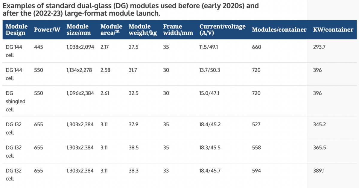
Today, modules with 550 W-plus nominal power – based on 182 mm wafers – and 210 mm-based, 650 W-plus products, are mainstream options for utility scale sites, typically with bifacial cells. Such panels require more, and larger cells, meaning larger, heavier modules, higher currents and lower voltage values. That has resulted in the most pluralised range of cell-to-module options ever seen.
Like any new PV technology, large-format modules come with hotly debated benefits and downsides. Despite impressive performance, larger modules are still not clear of challenges in terms of controlled and reliable use.
Developers and engineering, procurement, and construction (EPC) companies must consider the implications when deploying larger modules, including product quality and panel manufacturing processes, packaging and transportation, and tracker and inverter compatibility. These aspects must be taken into account before project design and procurement, to safeguard bankability.
Factory issues
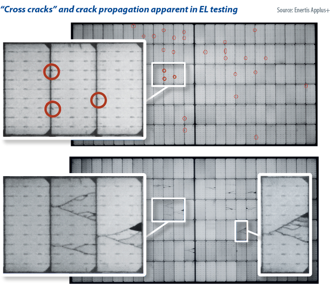
In the factory, a key, still unsettled issue to tackle during the manufacturing of larger modules is the so-called “cross-crack defect,” which is detectable by electroluminescence testing. As mentioned before, larger solar modules are based on new PV cell interconnections which can enable the reduction of non-active areas between solar cells to up to just a few millimetres, which partially mitigates product enlargement.
Still, these novel welding processes might lead to tiny, cross-shaped cracks in the vicinity of cell edges, seldom reported by manufacturers as a formal product defect despite their widespread occurrence. Unless it is duly negotiated and improved during the supply-agreement negotiation phase, this subtle defect may imply major on-site micro-crack propagation risks. Stress arising during cell soldering and lamination, plus the potential presence of chips at the wafer’s cut edges, facilitate the formation of such small cracks which can harmfully propagate upon mechanical loading application.
Larger modules are intrinsically prone to significant body deflections and torsions, free from any International Electrotechnical Commission (IEC) or Underwriters Laboratories (UL) standards. This stems from big surface areas – often exceeding 3 m2 – with the use of aluminium frames thinner than the typical 35 mm used in 400 W designs, driven by the need to optimise module weight of up to 40 kg. Weight reduction compels 3.2 mm glass substrates to be switched to the current 2 mm-plus-2 mm, dual glass architecture. Merging variables including higher area, shorter frame width, and thinner but heavier glass means a weaker module.
Glass quality is indeed a current challenge to consider, underscoring the need for bill-of-materials evaluation and approval prior to module production. Most suppliers declare in their constructional data forms and other documents that both front and rear glass are tempered, even though a simple audit check reveals quite the opposite on many occasions. Datasheets are confusing about the type of thermal treatment used in glass manufacturing, if any was used at all. As a result, sudden and unusually regular glass breakage incidences on mounted modules, mostly affecting the rear glass substrates, are being reported in many PV plants worldwide.
The flash test measurement of bifacial larger modules deserves further consideration when defining supply power bin distributions. The common 5 W datasheet’s interval, within the same module series, remains unchanged since early PV industry times, when around three-times-lower-powered panels were used. This may lead to less controlled nameplate power and module class sorting distribution, especially if several nameplate values are involved in the supply agreement – questioning whether more than one nameplate power is actually needed – and often triggering eventual changes in the total quantity of panels to comply with the total purchased power.
Also, the virtually, not-so-properly-established plus or minus 3% flash test uncertainty standard – amounting to a 16.5 W difference in a 550 W module – can lead to greater difficulties in filing power warranty claims and in rejecting lower-power, pre-shipment, laboratory inspection results, limiting the success ratio if test conditions and acceptance criteria are not duly settled in the supply agreement.
Finally, when measuring a larger module, the spatial uniformity of solar simulators should be a basic checkpoint to report during factory inspections, to avoid systematic errors potentially affecting the whole power output under purchase. Likewise, the use of more and larger cells per module may tend to a certain bifacial coefficient scattered distribution, which could play a role in determining PV plant design. Fortunately, as per our extensive experience of auditing factories and inspecting larger modules, manufacturers are making efforts to control these aspects properly, especially in brand-new production workshops and lines that do not require flash test system retrofits.
Logistical concerns
Larger modules are defined by increased area and weight. Consequently, logistics are affected one way or another. For instance, turning from a 400 W, M6-based module to an M12’s 650 W-plus implies an extra 30% surface area and load to pack and transport by sea and road. Despite cargo costs gradually decreasing since the container crisis hit worldwide markets in recent years, module manufacturers have built up innovative box packaging designs to optimise the kilowatts-peak of generation capacity shipped to sites.
Two main features were considered. The placement of modules in a portrait disposition within the box, implying new handling and safety guidelines to consider; and the use of thinner aluminium frames, even if module areas beyond 3 m2 were involved. Weight excess is also relevant in some locations, including some US states, because of regulated restrictions for road transportation, leading to potential situations in which container filling is limited, leaving empty spaces inside that must be properly managed in advance, outside the factory.
Problematic situations
Besides the aforementioned considerations and challenges ultimately impacting site activity and performance, a core concern was fast highlighted right after larger modules showed up on the market. That is, to what extent are solar trackers and inverters prepared for these devices?
The overall management of considerably bigger and heavier modules, based on lower voltages and greater currents, did bring about an intricate recipe to cook. At first, larger modules led to problematic situations requiring major reengineering tasks, as the 400 W-based versions used at development stages were no longer available a couple of years later when construction activity was set to commence.
Fortunately, this is no longer a major issue to address unless the context is associated with revamping or repowering activity, which requires a change from much older module designs to larger solar PV panels.
For DC/AC inverters, one can arguably say that most inverter manufacturers have become well adapted to the management of high current values. High currents do not imply significant challenges any more, beyond paying attention to the proper match between a maximum admissible current per input or maximum power point tracker in a string inverter and the maximum current of module output, including bifacial gains.
The same cannot be said about solar trackers, a problem caused by the still-suboptimal collaboration between modules which come in a range of dimensions, and tracker manufacturers. EPC contractors complete the trio as they juggle to optimise risk-cost ratios in a context of increased structure height and wind-exposed area, regardless of the use of 1P or 2P orientation configurations.
Tracker suppliers must reconsider several variables to enhance structural stiffness and reduce mechanical aeroelastic effects. Structural stiffness can be enhanced by using thicker hardware and reinforcements, at a cost. Mechanical aeroelastic effects such as torsional galloping at particular tilt angles, at even moderate wind speeds, can also be improved. Wind tunnel testing is not always available and not all laboratories are ready to test larger modules. And the occurrence of abnormally frequent windstorm events related to climate change, even in historically calm locations, makes tracker design tougher than ever.
Additionally, the module’s cantilever and deflection effects remain uncontrolled and unregulated by IEC/UL standards and manufacturer installation guidelines, regardless of the use of panel rails, clamps, or bolts in a structure.
Finally, the well-known unique current-voltage characteristics of larger modules makes possible the arrangement of longer module strings, potentially optimising project costs. Yet, in some cases, this feature may lead to design issues when trying to match the use of complete strings – based on 35 modules, for example – with tracker unit length.
Larger modules are here to stay as standard solar devices. Though all developers, EPC contractors, and technical advisors have been learning how to overcome the challenges stemming from the use of these big panels, there is an industry sentiment that module-area growth should cease at some point, and that PV module makers should eventually reach a standard product series that can be effortlessly adapted to any BOS equipment. The upcoming era of negatively-doped, n-type cells should pave the way to high-power modules based on device efficiency, rather than size.
 About the authors: Vicente Parra is director of quality assurance and quality control and technology at engineering consultancy Enertis Applus+. He has been a technical director at solar ingot, wafer, cell, and module manufacturers, has participated in technical, commercial, and procurement management of PV production expansion and has developed turnkey line PV module and cell manufacturing projects in Spain and France.
 James Whittemore, is quality assurance and quality control senior manager at Enertis Applus+. His PV manufacturing experience includes process engineering of thin-film CIGS(S) modules at Stion, process and equipment engineering of N-PASHA cells at Mission Solar, leading the quality, equipment, and process engineering departments in module manufacturing at Mission Solar, and leading operations at JinkoSolar’s US factory.
This content is protected by copyright and may not be reused. If you want to cooperate with us and would like to reuse some of our content, please contact: editors@pv-magazine.com.


By submitting this form you agree to pv magazine using your data for the purposes of publishing your comment.
Your personal data will only be disclosed or otherwise transmitted to third parties for the purposes of spam filtering or if this is necessary for technical maintenance of the website. Any other transfer to third parties will not take place unless this is justified on the basis of applicable data protection regulations or if pv magazine is legally obliged to do so.
You may revoke this consent at any time with effect for the future, in which case your personal data will be deleted immediately. Otherwise, your data will be deleted if pv magazine has processed your request or the purpose of data storage is fulfilled.
Further information on data privacy can be found in our Data Protection Policy.